Welcome To TUNKIA !      Electrical Measurement    Magnetic Measurement
You are here: Home » Products » AC DC Current Source and Meter » TH1300 DC High Current Sensor & Shunt Calibration System » TH1300 DC High Current Sensor and Shunt Calibration System

loading

Share to:
facebook sharing button
twitter sharing button
line sharing button
wechat sharing button
linkedin sharing button
pinterest sharing button
whatsapp sharing button
sharethis sharing button

TH1300 DC High Current Sensor and Shunt Calibration System

TH1300 can be fully automatic programmable output high precision, high stability, wide range of DC current, which can calibrate DC shunts and high-precision current sensors. It provides a reliable technical guarantee for the establishment of high-precision current and resistance transmission system for high-level metrology laboratories.

Availability:
Quantity:
  • TH1300 

  • TUNKIA

TH1300 DC High Current Sensor & Shunt Calibration System

TH1300 Calibration System for DC High Current Sensor and Shunt 3 

1. Summary

TH1300 can be fully automatic programmable output ± ( 0.1 mA~10 kA) with high precision, high stability, wide range of DC current. It is suitable for calibrating DC shunts with resistance value of 0.1 μΩ~100 kΩ, standard resistors, and also suitable for calibration of high-precision current sensors. It provides a reliable technical guarantee for the establishment of high-precision current and resistance transmission system for high-level metrology laboratories.

Equipped with three sets of bipolar current sources with different output ranges, all of which can be quickly commutated through program control, effectively removing the influence of thermoelectric potential on measurement and avoiding the disadvantage of poor contact with long-term relays Provide high reliability assurance for industrial-grade products for measurement and testing. Among them, TH6000 is a modular design of high-current sources, multiple current sources can be directly connected in parallel to generate ± ( 100A~10kA DC high current; TH1860 can accurately output ± ( 1 A ~ 1 1 0 A ) DC current, also  It is a constant current source with ultra-low noise, high precision, high linearity and better fineness; TH0740 A can output ± ( 0.1 mA~1 A ) DC current External standard resistors make precise measurements of the tested resistance.

The system is designed with two calibration schemes, direct measurement method and comparative method, to meet the calibration needs of different grades of shunts and sensors. (1) Direct measurement method: the use of bipolar current standard source with secondary signal measurement unit, can be 0.02 level and below DC shunt or current Fast automatic calibration of the sensor. (2) Comparative method: the use of bipolar current standard source with ultra-precision current proportional extender (can be cascaded), ultra-stable standard resistance, standard resistance measurement device through current polarity exchange can achieve ultra-high accuracy is suitable for calibrating 0.02 and above high-precision DC shunts and current sensors.

All components of the system can be controlled by computer software, and after the user is wired, it can realize automatic calibration, automatic saving of the original data of the inspected equipment, and automatic export/printing of calibration certificate.

2. Features

lTH6000 Bipolar High Current Source: powered by bidirectional power supply, internal circuit to achieve ± (100 A~10 kA) bipolar DC current programmable output. All range shifts do not use relays, which can realize fast commutation and range switching of high-current sources, effectively remove the influence of thermoelectric potential on resistance measurement, and avoid the shortcomings of poor contact with long-term relays. This bipolar current source scheme can provide high reliability assurance for industrial-grade products for metrological inspection.

Modular design of current source: using the combination output of multiple current sources, each current source has a built-in broadband current comparator for current measurement and control to ensure high stability and accuracy of current. Modular design improves maintenance efficiency even after maintenance; It is also easy to upgrade in the future, and the output range of the current can be expanded by adding a current source module, saving customers investment.

High stability and accuracy: the short-term stability of DC current output can reach 2.5ppm/min, 8ppm/h; Absolute accuracy of ±50 μ A/A. The software-controlled high current slowly rises and falls, reduces current surges, avoids power overshoot on the product under test, and provides a guarantee for high-precision sensor and shunt detection.

lTH1860 Bipolar Ultra-stable Constant Current Source: can accurately output ± ( 1 A~110 A) bipolar DC current, short-term stability up to 0 .4 ppm/min, 1.5ppm/h, absolute accuracy of ±15 μ A/A, is a constant current source with ultra-low noise, high precision, high linearity, and better fineness, which has been upgraded to an unprecedented level of accuracy and ultra-low noise in the commercial instrument market 

lTH0740A Standard Resistance Measuring Device: can accurately output ± (0.1 mA~1 A) bipolar DC current, external ultra-stable standard resistor, the realization range is 1Ω~ Quantity transmission of standard resistance of 100 kΩ; With dual-channel voltage ratio measurement function, with ultra-precision current proportional extender (can be cascaded), ultra-stable standard resistor and current polarity exchange can realize the range of 0.1 μ Ω~1 Ω ultra-high accuracy resistance or ratio transmission.

lUltra-stable Standard Resistance: It is an air-type standard resistance with an annual stability of 0 2 ppm, can be used at (23 ± 5)°C, and achieves ultra-high stability without the need for a thermostatic oil sump.

lStandard Resistance Multiplexer: multiple standard resistors of different specifications are connected at the same time, and according to the calibration requirements when used, the standard resistors of different specifications that have been accessed are switched by program control, reducing the user's repeated wiring steps and effectively improving the calibration efficiency.

lSensor Special Test Tooling: designed for the fast wiring of the through-core high-current sensor, equipped with a detachable current copper rod, which is conducive to the formation of a uniform magnetic field between the tested and the standard sensor, and further reduces the measurement error; And built-in sensor secondary signal measurement module and power supply module, can complete the proportional error, linearity error, power consumption and other detection items of the sensor.

lSpecial Test Position for Shunt: A special bracket for high-current wiring is designed to be a special device test position, which is convenient for accessing the DC shunt. With the high-precision shunt secondary voltage measurement module, the error detection of the shunt can be realized, and R(I), R(t) and other curves can be drawn.

lSystem Traceability: It can facilitate traceability calibration of large currents, either by tracing the independent output of a single current source, or by tracing the overall output of all current sources. 


3. Overall introduction of the system

TH1300 Calibration System for DC High Current Sensor and Shunt Overall introduction of the system


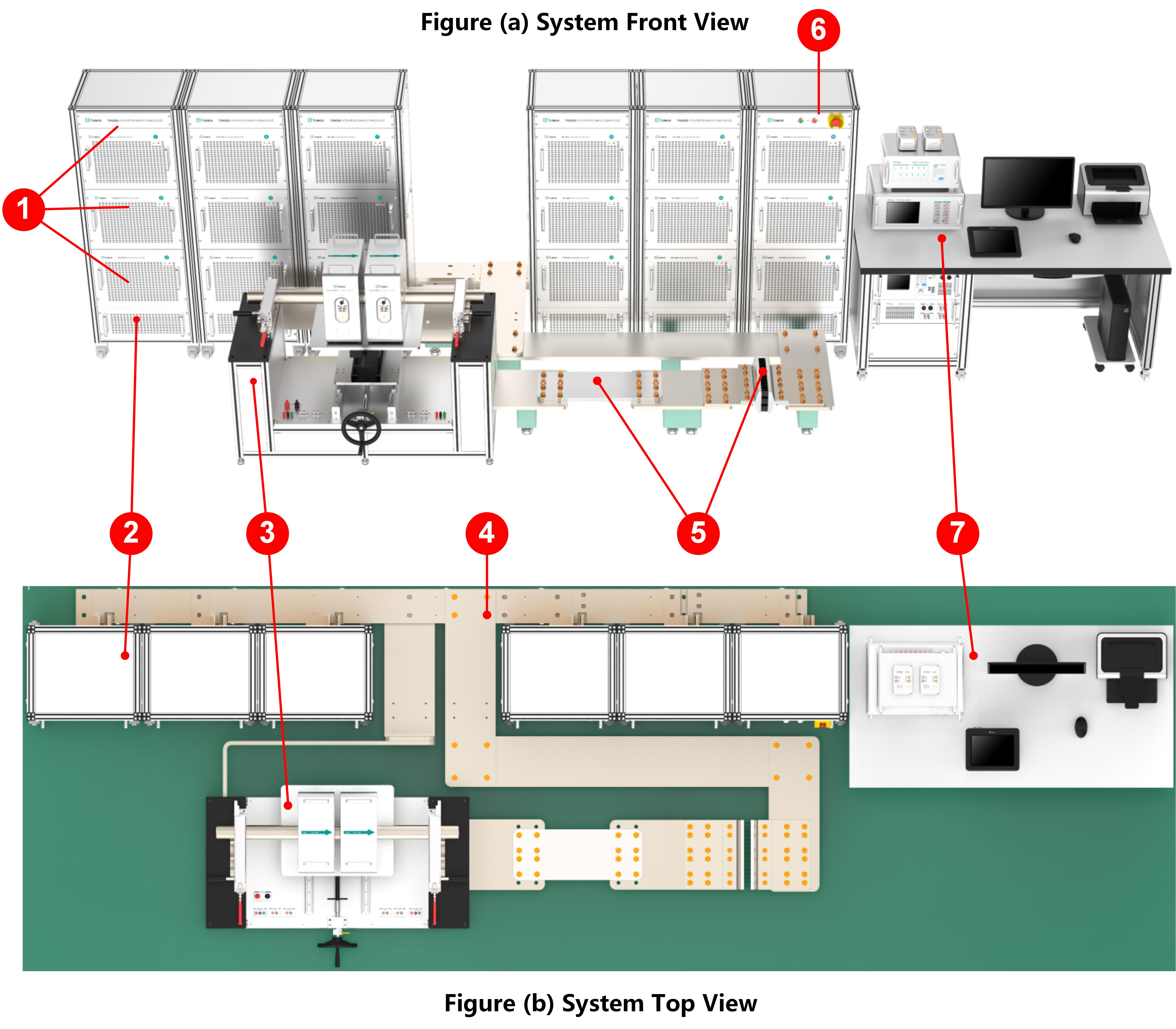
Figure 3-1 Schematic Diagram of the System Layout

NO.

Name

Brief introduction

 1

Single 600A Bipolar High Current Source

The complete system consists of a total of 6 current source cabinets. Each cabinet has three bipolar high-current sources with a maximum output of 600A, for a total of 18 current sources. Each source is equipped with an independent measurement and control module to ensure high current stability and accuracy.

The system can output ± bipolar DC high current (100 A~10 kA) through program-controlled output.

 2

Current Source Cabinet

 3

Sensor Test Bits

(1) Equipped with a set of sensor test tooling, equipped with a set of four specifications of deflector copper rod, which is convenient for the detection of the through-core sensor.

(2) The tooling panel is equipped with a set of sensor output signal tester (support the measurement and measurement of voltage and current signals) and auxiliary power supply interface, which is convenient for users to connect during testing.

 4

Confluence Copper Bar

The output current of each current source module is output through a specially designed copper bus.

 5

Shunt Test Bits

Includes two high-current test bits for calibration of shunts of different sizes.

When one test bit is connected to a DC shunt, the other test bit can be connected to a current ratio standard or shorted using a copper bar.

Start and Emergency Stop Buttons

Includes power switch and emergency stop button.

 7

Calibrate the Workbench

The calibration bench integrates the following devices:

TH1860-100A bipolar ultra-stable constant current source;

TH0740A standard resistance measuring device (built-in current, voltage ratio standard);

TH0780 Ultra-Precision Current Ratio Extender (Dual Channel);

TH0770 standard resistance multiplexer;

TH0330 Ultra-stable standard resistance (air type);

Measurement console, computer printing. See Figure 4-1 for details. 


4. Calibration Workbench

TH1300 Calibration System for DC High Current Sensor and Shunt Calibration Workbench

Figure 4-1 Schematic Diagram of the Calibration Bench

NO.

Name

Brief Introduction

TH0780 Ultra-precision Current Ratio Extender

It has a dual-channel ratio standard, where channel A has a maximum nominal current of 1 00 A, with 1 000:1, 1 00: 1, 1 0:1 three optional ratios;

The maximum nominal current of channel B is 1 0 A, with 1 00:1, 1 0:1 two select-able scales.

 2

TH1860-100A Bipolar Ultra-stable Constant Current Source

It can output ± (1A~110A) DC current, which is a constant current source with ultra-low noise, high precision, high linearity and better fineness.

TH0740A Standard Resistance Measuring Device

Precise output of ± ( 0 1 mA~1 A) DC current, external standard resistor to achieve precision measurement of 1 Ω~100 kΩ resistance; At the same time, it has the function of precision measurement of dual-channel voltage ratio.

 4

TH0770 Standard Resistance Multiplexer

According to the calibration requirements, the standard resistors of different specifications that have been connected are programmed to be switched.

 5

TH0330 Ultra-stable Standard Resistor

Standard resistors of different sizes are connected to the TH0770 and can be programmed to switch when used.

 6

Measurement Console

It can display the standard value of current output, the secondary small signal measurement value of the tested sensor or shunt, the error of the tested sensor or shunt, and the power consumption of the tested sensor in real time.

 7

Computer

Run the test software, and fully automatic testing can be realized according to user settings after wiring.

 8

Printer

Print the test report.


5. Sensor Test Fixture

TH1300 Calibration System for DC High Current Sensor and Shunt Sensor Test Fixture

Figure 5-1 Schematic Diagram of Sensor Test Fixture

NO.

Name

Brief introduction

Quick Clamps

The left and right sides are equipped with a set of quick clamps that can be manually opened and clamped with copper rods with a clamping force of 250kg, each with four clamping holes of different diameters.

 2

Copper Rods

According to the size of the test current, different diameters of copper rods are selected, and the sensor is penetrated during the test, which is conducive to forming a uniform magnetic field between the tested and the standard sensor, further reducing the measurement error.

Note: Copper rod current specifications: 10 kA, 5 kA, 2  kA, 1kA

 3

Sensor Test Bits

It can be penetrated into the penetrated core current sensor and the through-core current proportional extender.

 4

Low Current Output

For sensor testing with smaller current specifications.

Sensor-assisted Measurement

(1) The power supply module can output DC ± (5 V~50 V) programmable adjustable voltage It also has the function of loop current and power measurement to detect the power consumption of the sensor.

(2) Support the measurement of secondary voltage signal or current signal of the sensor.

Foldable Hand Wheel

Turn the hand wheel sensor platform to lift and move back and forth.

Sensor Platform

It can be controlled by a hand wheel to put sensors of different sizes in the appropriate test position.


6. How The System Works

6.1 Shunt Calibration (Direct Measurement Method)

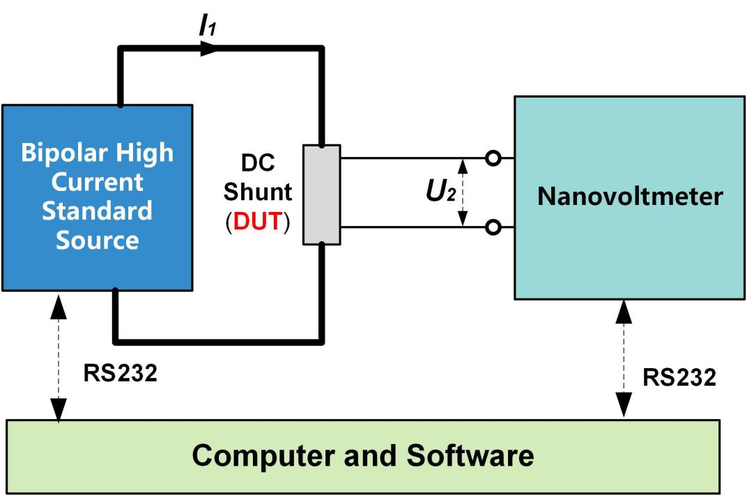
The software automatically controls the rapid commutation of the current source to remove the effects of the thermoelectric potential. This method is suitable for DC shunts with lower accuracy of class 0.02 and below, and can achieve automatic and fast measurement.
TH1300 Calibration System for DC High Current Sensor and Shunt Schematic Diagram of Calibrating a DC Shunt by Direct Measurement

Figure 6-1 Schematic Diagram of Calibrating a DC Shunt by Direct Measurement

Description of the test:

A bipolar high-current source is used to output a standard current as theI1 input to the DC shunt under test.

Measure the secondary output voltage U2 of the shunt under test directly using a nanovoltmeter.

After the shunt reaches thermal equilibrium, the resistance of the shunt is calculated according to R=U 2I1.

After the user has completed the wiring, fully automatic calibration can be realized through the computer and system software.


6.2 Shunt Calibration (Comparative Method)

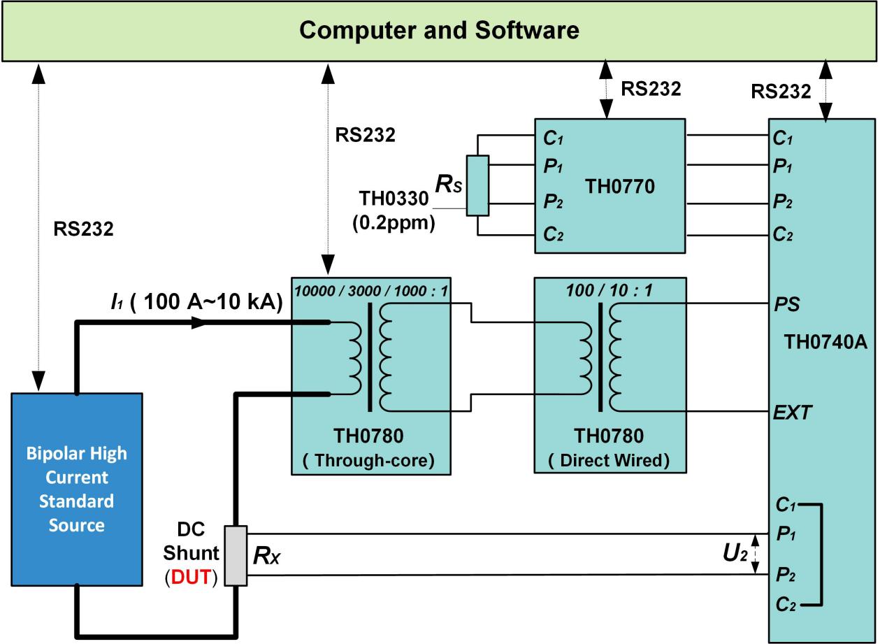
Comparative method features: the use of bipolar high-current standard source with ultra-precision current proportional extender (can be cascaded), ultra-stable standard resistance, standard resistance measurement device through current polarity exchange can achieve ultra-high accuracy resistance transmission, suitable for calibrating 0.02 and above high-precision DC shunt, by the software automatically control the rapid commutation of the current source to remove the influence of thermoelectric potential.
TH1300 Calibration System for DC High Current Sensor and Shunt Schematic Diagram of a Calibrated DC Shunt (I1≥100A) by Comparative Method

Figure 6-2-1 Schematic Diagram of a Calibrated DC Shunt (I1≥100A) by Comparative Method


Description of the test:

For DC shunt calibration with nominal current I 1≥100 A, a bipolar high-current source is used to output a standard current as the I1 input to the shunt under test, and 1 000:1, 3 000 are selected according to the input current The TH 0780 ultra-precision current ratio extender of three specifications: 1, 1 0000:1 is connected in series with the primary side of the shunt under test.

The secondary output of the high-current TH 0780 is connected to the integrated TH 0780 in a dual-channel chassis, and its secondary output is connected to the external excitation input of the TH0740 A.

Connect the TH0330 ultra-stable standard resistor with a known resistance value to the A channel of the TH 0740 A (the user can program the TH0770 to switch the standard resistor with different resistance specifications).

The B-channels P 1 and P 2 of the output voltage TH0740 A of the shunt will be shortened to terminals C 1 and C2.

When the TH0740A internal bridge is balanced, the resistance of the shunt under test is measured.

After the user has completed the wiring, fully automatic calibration can be realized through the computer and system software.


TH1300 Calibration System for DC High Current Sensor and Shunt 6-3 Schematic Diagram of a Calibration DC Shunt (1 A ≤ I1 ≤ 100 A) by Comparative Method

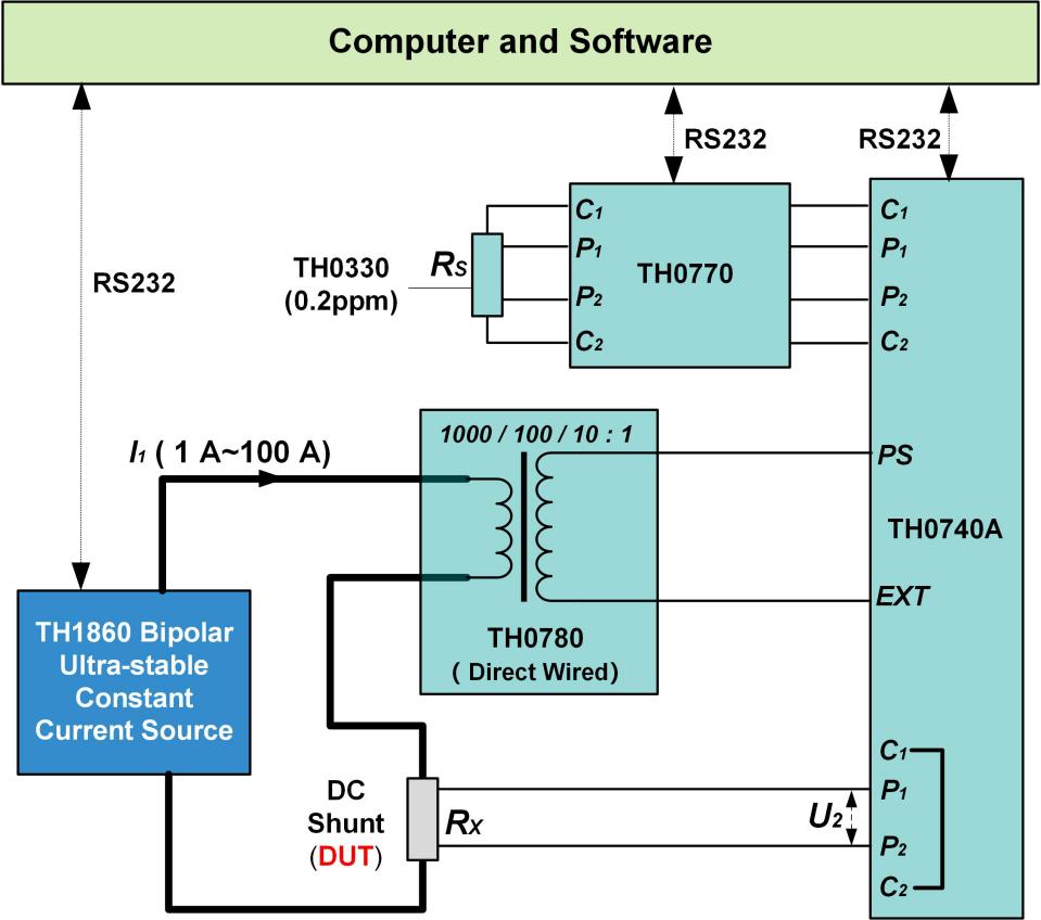
Figure 6-2-2 Schematic Diagram of a Calibration DC Shunt (1 A ≤ I1 ≤ 100 A) by Comparative Method


Description of the test:

For the calibration of DC shunts with a nominal current of less than or equal to 100 A, the TH 1860 ultra-stable constant current source is used to output a standard current as the I1 input to the sensor under test.

Pass the I 1 into the primary side of the TH0780 Ultra-Precision Current Proportional Extender (integrated in a dual-channel chassis) and the system automatically selects 1 000:1, 100:1,1 0 based on the input current : 1 scale; Its secondary output is connected to the external excitation input of the TH0740A.

Connect the TH 0330 ultra-stable standard resistor with known resistance value to the A channel of the TH 0740 A (the user can program the TH0770 to switch the standard resistor with different resistance specifications).

The B-channels P 1 and P 2 of the output voltage TH0740 A of the shunt will be shortened to terminals C 1 and C2.

When the TH0740A internal bridge is balanced, the resistance of the shunt under test is measured.

After the user has completed the wiring, fully automatic calibration can be realized through the computer and system software.


6.3 For DC shunts or standard resistors with nominal current of 0.1 mA ≤ I1 ≤ 1 A, TH 0330 and TH can be used directly 0740A direct calibration.
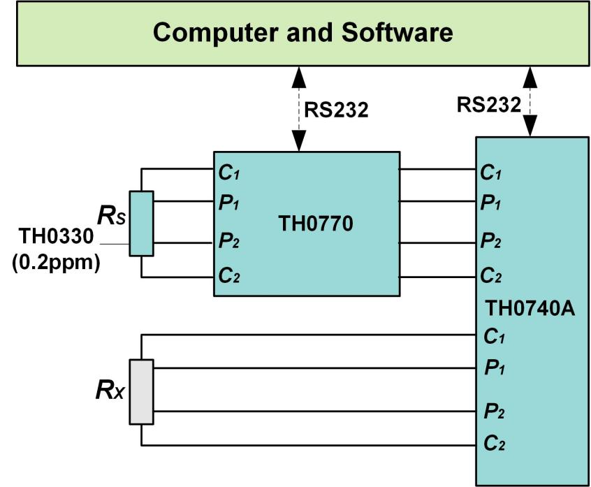
TH1300 Calibration System for DC High Current Sensor and Shunt 6-4 Schematic Diagram of a Calibration DC Shunt (0.1mA ≤ I1 ≤ 1 A) by Comparative Method

Figure 6-3 Schematic Diagram of a Calibration DC Shunt (0.1mA I1 ≤ 1 A) by Comparative Method


Description of the test:

Connect a TH0330 ultra-stable standard resistor of known value to the A channel of TH 0740 A

(Note: Users can switch standard resistors with different resistance specifications through TH0770 program control).

The DC shunt or standard resistor is connected to the B channel of the TH0740A.

When the TH0740A internal bridge is balanced, the resistance of the shunt under test is measured.

After the user has completed the wiring, fully automatic calibration can be realized through the computer and system software.


6.4 Sensor Calibration (Direct Measurement Method)

This method is suitable for sensor testing with lower accuracy of class 0.02 and below, enabling fast and automated measurements.

TH1300 DC High Current Sensor and Shunt Calibration System

Figure 6-4-1 Schematic Diagram of Calibrating The Sensor by Direct Measurement

Description of the test:

A bipolar high-current source is used to output a standard current as theI1 input to the sensor under test.

The current signal I 2 (current type) or voltage signal U2 (voltage type) output by the tested sensor is connected to the secondary signal measurement unit of the sensor, and the primary current I1 is combined to realize the calibration of the sensor ratio.

After the user has completed the wiring, fully automatic calibration can be realized through the computer and system software.


6.5 Sensor Calibration (Comparative Method)

Comparative method features: the use of bipolar high-current standard source with ultra-high accuracy ultra-precision current proportional extender (can be cascaded), ultra-stable standard resistance, standard resistance measurement device through current polarity exchange can achieve ultra-high accuracy ratio transmission, suitable for calibrating 0.02 level and above high-precision current sensors.
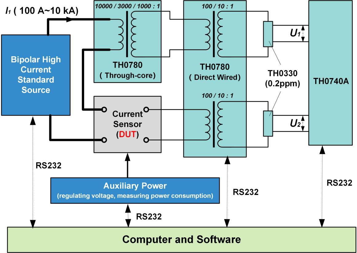
TH1300 DC High Current Sensor and Shunt Calibration System

Figure 6-5-1 Schematic diagram of a calibrated sensor (I1≥100A) by comparative method

Description of the test:

For the calibration of current sensors with a nominal current greater than or equal to 1 00 A, a bipolar high-current source is used to output a standard current as the I1 input to the sensor under test, and 1 000:1, 3 000:1, 10000 are selected according to the input current :1 The TH0780 ultra-precision current proportional extender of three sizes is connected in series with the primary side of the sensor under test.

The secondary output of the tested sensor and the high-current specification TH 0780 is connected to the integrated TH0780 of the dual-channel chassis, and the secondary output of the dual channel is connected to two TH 0330 ultra-stable standard resistors with known resistance values for I/V conversion.

Then connect the voltage signals U1 and U2 of the two standard resistors to TH0740A for voltage ratio measurement.

After the user has completed the wiring, fully automatic calibration can be realized through the computer and system software.
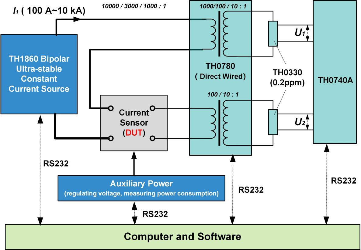
TH1300 DC High Current Sensor and Shunt Calibration System

Figure 6-5-2 Schematic Diagram of a Calibrated Sensor (I1≤100A) by Comparative Method


Description of the test:

For the calibration of current sensors with a nominal current of less than or equal to 1 00 A, the TH 1860-100A ultra-stable constant current source is used to output the standard current as the I1 input to the tested sensor; Pass I 1 into the primary side of the A channel of the TH0780 ultra-precision current proportional extender (integrated in a dual-channel chassis), and the system automatically selects 1 000:1, 100:1, 1 based on the input current 0:1 ratio.

The secondary output of the sensor under test is connected to the primary side of the B channel of the TH0780.

The dual secondary outputs of the TH0780 are connected to two TH 0330 ultra-stable standard resistors of known resistance for I/V conversion.

Then connect the voltage signals U1 and U2 of the two standard resistors to TH0740A for voltage ratio measurement.

After the user has completed the wiring, fully automatic calibration can be realized through the computer and system software.

7. Specifications

7.1 TH6000 Bipolar DC High Current Source

Range

Resolution

Short-term Stability

Measurement Uncertainty (k=2).

ppm*RD+ppm*RG

Maximum Load Voltage

(V)

ppm/min

ppm/h

1 year

500 A

100 μA

2.5

8.0

30 + 20

3

1 kA

1mA

2.5

8.0

30 + 20

3

2 kA

1mA

2.5

8.0

30 + 20

3

5 kA

1mA

2.5

8.0

30 + 20

3

10 kA

10 mA

2.5

8.0

30 + 20

3

  • Output range: ± (100 A ~ 10 kA), manual or program-controlled automatic switching

  • Fineness adjustment: 10 ppm*RG, 7-digit decimal display

  • Ripple coefficient: <0.5% @ 5 kHz or less, overshoot coefficient: <5%.

  • Full-scale output settling time: < 500ms

  • Protection function: current open circuit protection, overload protection, overtemperature protection

  • Note: RD is the reading value, RG is the range value, the same below


7.2 TH1860 Bipolar Ultra-stable Constant Current Source

current

Range

Resolution

( mA )

Short-term Stability

ppm /min

Maximum allowable Error

± ( ppm*output + ppm*range )

24 hours

1 year

10 A

1

0.4

5 + 5

10 + 5

100 A

10

0.4

5 + 5

10 + 5

  • Output range: ± (1   A ~ 110 A), display bits: 7 bits, adjustment fineness: 2ppm;

  • Settling time: the time from setting the output to meet the requirements of the index is less than 100 ms;

  • Test conditions: 1 hour preheating, ambient temperature 23°C±1°C, sampling rate of 1sps;

  • Protection mode: open circuit protection, over temperature protection, overload protection.


7.3 TH0780 Ultra-precision Current Proportional Extender

Product Model

Product Name

Input Current

(A)

Output Current

(A)

Proportion

Accuracy

(ppm)

TH0780-1A

Ultra-precision current proportional extender

(integrated in one chassis).

1

0.1

10:1

0.2

TH0780-10A

10

0.1

100:1

0.2

TH0780-100A

100

0.1

1000:1

0.5

TH0780-1kA

1kA ultra-precise current proportional extender

1,000

1

1000:1

1.5

TH0780-3kA

3kA ultra-precise current proportional extender

3,000

1

3000:1

3.0

TH0780-10kA

10kA ultra-precise current proportional extender

10,000

1

10000:1

10


7.4 TH0330 Ultra-stable Standard Resistor (Air Type)

Nominal Value

Initial Deviation

( ppm)

Temperature Coefficient

( ppm /℃)

@23± 5℃

Year Stability

( ppm )

Rated Power

( W )

Power Factor

( ppm /power* )

1 H

± 2

± 0.05

± 0.2

1.0

± 1

10 Ω

± 2

± 0.05

± 0.2

1.0

± 1

100 Ω

± 2

± 0.05

± 0.2

1.0

± 1

1 kΩ

± 2

± 0.05

± 0.2

1.0

± 1

Note: TH0330 is an air-type standard resistor, with two of each specification

  • Working temperature: 18 °C ~ 28 °

  • CStorage temperature: 0~50°C

  • Number of pins: 5


7.5 TH0740A Standard Resistance Measuring Device

DC Standard Resistance Measurement

Standard resistors

( Z )

Resolution

( Z )

Test the current

( A )

Test the power

( mW )

Measurement uncertainty (k=2)

( ppm )

1

10 n

100 m

10

0.2

10

100 n

31.6 m

10

0.2

100

1 m

10 m

10

0.5

1 k

10 m

3.16 m

10

0.5

10 k

100 m

1 m

10

2

100 k

1 m

0.1 m

1

3

Note: Current ratio range: 1:1~100:1, ratio uncertainty: 0.15 ppm


Voltage Ratio Uncertainty ( k= 2 )  ( ppm )

U1 range

U2 range

1 mV

10 mV

100 mV

1 V

10 V

1 mV

5 ( 0.5 ≤ K ≤ 2 )

10 (0.1 ≤ K < 0.5or2 < K < 10)

40 ( 1 < K ≤ 2 )

80 ( 2 < K< 10)

——

——

——

10 mV

40 ( 1 < K ≤ 2 )

80 ( 2 < K < 10)

3 ( 0.5 ≤ K ≤ 2 )

8 (0.1 ≤ K < 0.5or2 < K < 10)

10 ( 1 < K ≤ 2 )

30 ( 2 < K < 10)

——

——

100 mV

——

10 ( 1 < K ≤ 2 )

30 ( 2 < K < 10)

1 ( 0.5 ≤ K ≤ 2 )

4 (0.1 ≤ K < 0.5or2 < K < 10)

3 ( 1 < K ≤ 2 )

8 ( 2 < K < 10)

——

1 V

——

——

3 ( 1 < K ≤ 2 )

8 ( 2 < K < 10)

0.5 ( 0.5 ≤ K ≤ 2 )

2 (0.1 ≤ K < 0.5or2 < K < 10)

1.5 ( 1 < K ≤ 2 )

4 ( 2 < K < 10)

10 V

——

——

——

1.5 ( 1 < K ≤ 2 )

4 ( 2 < K < 10)

0.5 ( 0.5 ≤ K ≤ 2 )

2 (0.1 ≤ K < 0.5or2 < K < 10)

Note: K = U1 / U2 if measured K > 10 or K < 0.1, should be replaced with the current proportional extender closest to the UUT ratio.


7.6 TH0770 Standard Resistor Multiplexer

Specification

Four-terminal channel

Connection Type

Copper tellurium terminal posts

Input Channel

10 channels (rear panel)

Output Channel

Single channel (rear panel)

Thermal Electromotive Force

< 50 nV

Maximum Carry / Switch Current

2 A @ 30 VDC

Contact Resistance

< 0.05 h

Communication Interface

RS232


7.7 Shunt Resistance Measurement (Comparative Method)

The Value of the Resistance to be Measured

Proportion

Maximum Current

Measurement Uncertainty ( k=2 ).

100 mΩ

101

1 A

0.2 ppm

10 mΩ

1001

10 A

0.3 ppm

1 mΩ

10001

100 A

0.4 ppm

100 mΩ

100001

1 kA

2 ppm

10 mΩ

1000001

3 kA

3 ppm

1 mΩ

100000 01

5 kA

5 ppm

0.1 mΩ

100000 01

10 kA

10 ppm


7.8 TK1230 Sensor Output Signal Tester

Electricity

type

Range

Resolution

Measurement Uncertainty (k=2)

ppm*RD+ppm*RG

Temperature Coefficient

ppm*RG/°C

24 hours

90 days

1 year

voltage

measurement

100 mV

100nV

10 + 5

15 + 5

20 + 10

<0.5

1 V

1 μV

10 + 5

15 + 5

20 + 10

<0.5

10 V

10 μV

10 + 5

15 + 5

20 + 10

<0.5

current

measurement

10 mA

10 nA

10 + 5

15 + 5

20 + 10

<0.7

100 mA

100 nA

10 + 5

15 + 5

20 + 10

<0.7

1 A

1μA

10 + 5

15 + 5

20 + 10

<0.7

  • Measuring range: ± (10 mV~12 V), ± (1 mA~1.1 A)

  • Range switching: manual or automatic switching

  • Display digits: 7-digit decimal display

  • Voltage measurement input impedance: >100kΩ // 50pF


7.9 Sensor auxiliary power supply and power consumption measurement

  • Output range: DC ±(5~50) V, maximum load capacity: 1 A

  • Adjustment mode: the output voltage value can be set by the touch screen or computer software programmatically

  • Fineness adjustment: 0 1 V

  • Protection function: short circuit protection, overload protection, overtemperature protection

  • Measurement function: with voltage, current, power measurement, to realize the power consumption measurement function of the sensor.

  • Voltage/current accuracy is ±0.2% and power measurement accuracy is ±0.5%.


8. Installation

8.1 Floor Plans


TH1300 Calibration System for DC High Current Sensor and Shunt scheme layout 

Figure 8-1 schematic diagram of the scheme layout

The entire system occupies a single area

5700 mm×1850 mm(L×W)

Single cabinet size

560 mm×560 mm×1500 mm(W×L×H)

Laboratory size is recommended

66 00mm×3000 mm(L×W)


8.2 Power supply requirements

S/N

Device Name

Type of Power Supply

Maximum Power Consumption

Quantity

Total Power Consumption

1

600 A Bipolar High Current Source Module

Three-phase Four-Wire System

AC 380V

4 kW

18 units

72kW

2

TK1230 Sensor Output Signal Tester

0.1 kW

1 set

0.1 kW

3

Sensor Power Supply And Power Consumption Test Module

0.1 kW

1 set

0.1 kW

4

High Current Source Main Control System

2 kW

1 set

2 kW

5

TH1860 Bipolar Ultra-Stable Constant Current Source

Single-phase AC 220V

0.2 kW

1 unit

0.2 kW

6

TH0740A Standard Resistance Measuring Device

Single-phase AC 220V

0.1kwatts

1 set

0.1 kW

7

TH0770 Standard Resistance Multiplexer

Single-phase AC 220V

0.1kwatts

1 set

0.1 kW

8

TH0780 Ultra-Precision Current Ratio Extender

Single-phase AC 220V

0.1kwatts

1 set

0.1 kW

9

Computers and Printers

Single-phase AC 220V

0.5 kW

1 set

0.5 kwatts

Total power consumption for the entire system

Approx 75 kW

Previous: 
Next: 

SIGN UP FOR NEWSLETTER

Get latest deals, newsletter and technical information

INFORMATION

CONTACT US

 WhatsApp:+86-18773180215
     Wechat: 18773180215
 Phone: +86-18773180215
 E-mail: global@tunkia.com
E-mail: Eugene@tunkia.com
 Address: NO.16 Panpan Road, Changsha
Copyright  2021 TUNKIA Co., Ltd. All Rights Reserved. Supported by leadong.comSitemap