6. Specifications of TD1880 Precision Multifunction Calibrator
6.1 DC Voltage Output of TD1880 Multifunction Calibrator
Range | Resolution | Accuracy (k=2)(Tcal±5°C) ppm*output + μV | Stability (Tcal±1°C) ppm*output + μV | Maximum Load [Internal Impedance] |
| 90 days | 1 year | 24 hours |
0~330.0000 mV | 100 nV | 15 + 1.5 | 20 + 1.5 | 3 + 1 | [60 Ω] |
0~3.300000 V | 1 μV | 8 + 3 | 10 + 3 | 2 + 1.5 | 20 mA |
0~33.00000 V | 10 μV | 10 + 30 | 12 + 30 | 2 + 10 | 15 mA |
30.0000 V~330.0000 V | 100 μV | 15 + 200 | 18 + 200 | 2.5 + 100 | 10 mA |
100.000 V~1020.000 V | 1 mV | 15 + 2000 | 18 + 2000 | 3 + 300 | 10 mA |
• Manual or automatic range switch.
• Short-circuit and overload protection.
6.2 DC Current Output of TD1880 Multifunction Calibrator
Range | Resolution | Accuracy (k=2)(Tcal±5°C) ppm*output + μA | Compliance Voltage (V) | Max Inductive Load |
90 days | 1 year |
0~330.0000 μA | 100 pA | 80 + 0.02 | 100 + 0.02 | 11 V | 400 μH |
0~3.300000 mA | 1 nA | 65 + 0.03 | 80 + 0.03 | 11 V |
0~33.00000 mA | 10 nA | 60 + 0.25 | 80 + 0.25 | 9 V |
0~330.0000 mA | 100 nA | 60 + 2 | 80 + 2 | 7 V |
0~1.100000 A | 1 μA | 80 + 20 | 100 + 20 | 6 V |
1.000000 A~3.300000 A | 1 μA | 120 + 50 | 150 + 50 | 6 V |
3.00000 A~20.50000 A | 10 μA | 280 + 300 | 350 + 300 | 4 V |
• Manual or automatic range switch.
• Open-circuit and overload protection.
• Supports continuous and long-term output of current under full range.
6.3 Simulated DC Resistance of TD1880 Multifunction Calibrator
Range | Resolution | Accuracy(k=2) (Tcal±5°C) ppm*output + Ω | Allowable Current |
90 days | 1 year |
0 Ω~11.00000 Ω | 10 μΩ | 32 + 0.008 | 40 + 0.01 | 1 mA~150 mA |
10.00000 Ω~33.00000 Ω | 10 μΩ | 24 + 0.012 | 30 + 0.015 | 1 mA~150 mA |
30.0000 Ω~110.0000 Ω | 100 μΩ | 20 + 0.012 | 25 + 0.015 | 1 mA~80 mA |
100.0000 Ω~330.0000 Ω | 100 μΩ | 20 + 0.016 | 25 + 0.02 | 1 mA~40 mA |
0.300000 kΩ~1.100000 kΩ | 1 mΩ | 20 + 0.016 | 25 + 0.02 | 1 mA~20 mA |
1.000000 kΩ~3.300000 kΩ | 1 mΩ | 20 + 0.16 | 25 + 0.1 | 0.1 mA~6 mA |
3.00000 kΩ~11.00000 kΩ | 10 mΩ | 20 + 0.16 | 25 + 0.2 | 0.1 mA~2 mA |
10.00000 kΩ~33.00000 kΩ | 10 mΩ | 22 + 0.8 | 28 + 1 | 10 μA~0.6 mA |
30.0000 kΩ~110.0000 kΩ | 100 mΩ | 22 + 0.8 | 28 + 1 | 10 μA~0.2 mA |
100.0000 kΩ~330.0000 kΩ | 100 mΩ | 25 + 8 | 32 + 10 | 1 μA~60 μA |
0.300000 MΩ~1.100000 MΩ | 1 Ω | 25 + 8 | 32 + 10 | 1 μA~20 μA |
1.000000 MΩ~3.300000 MΩ | 1 Ω | 40 + 120 | 60 + 150 | 0.25 μA~6 μA |
3.00000 MΩ~11.00000 MΩ | 10 Ω | 104 + 200 | 130 + 250 | 0.25 μA~2 μA |
10.00000 MΩ~33.00000 MΩ | 10 Ω | 200 + 2500 | 250 + 2500 | 25 nA~600 nA |
30.0000 MΩ~110.0000 MΩ | 100 Ω | 400 + 3000 | 500 + 3000 | 25 nA~200 nA |
100.0000 MΩ~330.0000 MΩ | 100 Ω | 2400 + 100000 | 3000 + 100000 | 2.5 nA~60 nA |
300.000 MΩ~1100.000 MΩ | 1 kΩ | 11000 + 480000 | 14000 + 480000 | 1 nA~20 nA |
• Output is continuously adjustable.
• Manual or automatic range switch.
• Over-current and reverse connection protection.
6.4 AC Voltage (Sine Wave)Output of TD1880 Multifunction Calibrator
Range | Frequency (Hz) | Accuracy (k=2) (Tcal±5°C) ppm*output + μV | Resolution | Max Load [Source internal resistance] |
90 days | 1 year |
1.00000 mV~ 33.00000 mV | 10≤F≤45 | 600 + 6 | 800 + 6 | 10 nV | [10 Ω] |
45<F≤10k | 100 + 6 | 120 + 6 |
10k<F≤20k | 160 + 6 | 200 + 6 |
20k<F≤50k | 800 + 6 | 1000 + 6 |
50k<F≤100k | 2800 + 12 | 3500 + 12 |
100k<F≤500k | 6000 + 50 | 8000 + 50 |
30.0000 mV~ 330.0000 mV | 10≤F≤45 | 250 + 8 | 300 + 8 | 100 nV | [60 Ω] |
45<F≤10k | 112 + 8 | 140 + 8 |
10k<F≤20k | 130 + 8 | 160 + 8 |
20k<F≤50k | 280 + 8 | 350 + 8 |
50k<F≤100k | 600 + 20 | 750 + 20 |
100k<F≤500k | 1600 + 70 | 2000 + 70 |
0.300000 V~ 3.300000 V | 10≤F≤45 | 250 + 50 | 300 + 50 | 1 μV | 20 mA |
45<F≤10k | 80 + 50 | 100 + 50 |
10k<F≤20k | 150 + 50 | 180 + 50 |
20k<F≤50k | 240 + 50 | 300 + 50 |
50k<F≤100k | 550 + 100 | 700 + 100 |
100k<F≤500k | 2000 + 600 | 2400 + 600 |
3.00000 V~ 33.00000 V | 10≤F≤45 | 160 + 650 | 200 + 650 | 10 μV | 15 mA |
45<F≤10k | 80 + 500 | 100 + 500 |
10k<F≤20k | 160 + 500 | 200 + 500 |
20k<F≤50k | 280 + 500 | 350 + 500 |
50k<F≤100k | 350 + 1500 | 550 + 1500 |
30.0000 V~ 330.0000 V | 45≤F≤1k | 80 + 2000 | 100 + 2000 | 100 μV | 30 mA [1] |
1k<F≤10k | 80 + 6000 | 100 + 6000 |
10k<F≤20k | 160 + 6000 | 200 + 6000 |
20k<F≤50k | 240 + 6000 | 300 + 6000 |
50k<F≤100k | 1200 + 50000 | 1500 + 50000 |
300.000 V~ 1020.000 V | 45≤F≤1k | 100 + 10000 | 120 + 10000 | 1 mV | 8 mA [2] |
1k<F≤5k | 120 + 10000 | 150 + 10000 |
5k<F≤10k | 160 + 10000 | 200 + 10000 |
| Note[1]: When the output frequency is ≤3kHz, the maximum load is 30 mA; when the output frequency is >3kHz, the maximum load is 5 mA. Note[2]: When the output frequency is ≤3kHz, the maximum load is 8 mA; when the output frequency is >3kHz, the maximum load is 3 mA. |
•Range switching: manual shifting, automatic shifting
•Protection function: short circuit protection, overload protection
6.5 AC Current(Sine Wave) Output of TD1880 Multifunction Calibrator
Range | Frequency (Hz) | Accuracy (k=2) (Tcal±5°C) %* output + μA | Resolution | Compliance Voltage (rms) | Max Inductive Load (μH) |
90 days | 1 year |
29.0000 μA~ 330.0000 μA | 10≤F≤20 | 0.08 + 0.1 | 0.1 + 0.1 | 0.1 nA | 7 V | 200 |
20<F≤45 | 0.04 + 0.1 | 0.05 + 0.1 |
45<F≤1k | 0.024 + 0.1 | 0.03 + 0.1 |
1k<F≤5k | 0.08 + 0.1 | 0.1 + 0.1 |
5k<F≤10k | 0.16 + 0.2 | 0.2 + 0.2 |
10k<F≤30k | 0.64 + 0.4 | 0.8 + 0.4 |
0.300000 mA~ 3.300000 mA | 10≤F≤20 | 0.04 + 1.5 | 0.05 + 1.5 | 1 nA | 7 V | 200 |
20<F≤45 | 0.028 + 0.1 | 0.035 + 0.1 |
45<F≤1k | 0.024 + 0.1 | 0.03 + 0.1 |
1k<F≤5k | 0.024 + 0.2 | 0.03 + 0.2 |
5k<F≤10k | 0.024 + 0.5 | 0.03 + 0.5 |
10k<F≤30k | 0.16 + 0.6 | 0.2 + 0.6 |
3.00000 mA~ 33.00000 mA | 10≤F≤20 | 0.04 + 2 | 0.05 + 2 | 10 nA | 7 V | 50 |
20<F≤45 | 0.02 + 2 | 0.025 + 2 |
45<F≤1k | 0.016 + 2 | 0.02 + 2 |
1k<F≤5k | 0.016 + 3 | 0.02 + 3 |
5k<F≤10k | 0.04 + 5 | 0.05 + 5 |
10k<F≤30k | 0.16 + 6 | 0.2 + 6 |
30.0000 mA~ 330.0000 mA | 10≤F≤20 | 0.04 + 20 | 0.05 + 20 | 100 nA | 5 V | 50 |
20<F≤45 | 0.02 + 20 | 0.025 + 20 |
45<F≤1k | 0.012 + 30 | 0.015 + 30 |
1k<F≤5k | 0.016 + 30 | 0.02 + 30 |
5k<F≤10k | 0.016 + 100 | 0.02 + 100 |
10k<F≤30k | 0.08 + 500 | 0.1 + 500 |
0.100000 A~ 1.100000 A | 10≤F≤20 | 0.04 + 100 | 0.05 + 100 | 1 μA | 5 V | 2.5 |
20<F≤45 | 0.024 + 50 | 0.03 + 50 |
45<F≤1k | 0.016 + 50 | 0.02 + 50 |
1k<F≤5k | 0.016 + 100 | 0.02 + 100 |
5k<F≤10k | 0.04 + 500 | 0.05 + 500 |
1.000000 A~ 3.300000 A | 10≤F≤20 | 0.04 + 100 | 0.05 + 100 | 1 μA | 4 V | 2.5 |
20<F≤45 | 0.024 + 100 | 0.03 + 100 |
45<F≤1k | 0.016 + 100 | 0.02 + 100 |
1k<F≤5k | 0.032 + 100 | 0.04 + 100 |
5k<F≤10k | 0.04 + 900 | 0.05 + 900 |
3.00000 A~ 20.50000 A | 45≤F≤100 | 0.024 + 1000 | 0.03 + 1000 | 10 μA | 3 V | 1 |
100<F≤1k | 0.032 + 1000 | 0.04 + 1000 |
1k<F≤5k | 0.048 + 2000 | 0.06 + 2000 |
•Manual or automatic range switch.
•Open-circuit and overload protection.
•Supports continuous and long-term output of current under full range.
6.6 Sinusoidal Wave Frequency Output of TD1880 Multifunction Calibrator
Range [1] | Resolution | Accuracy (k=2) (Tcal±5°C) |
10.00000 Hz ≤ F ≤ 99.99999 Hz | 10 μHz | 0.005% |
100.0000 Hz ≤ F ≤ 999.9999 Hz | 0.1 mHz | 0.005% |
1.000000 kHz ≤ F ≤ 9.999999 kHz | 1 mHz | 0.005% |
10.00000 kHz ≤ F ≤ 99.99999 kHz | 10 mHz | 0.005% |
100.0000 kHz ≤ F ≤ 500.0000 kHz | 0.1 Hz | 0.005% |
| Note [1]: Output mode: AC voltage or AC current |
6.7 DC Power Output of TD1880 Multifunction Calibrator
Period | Current Range Voltage Range | Accuracy (k=2) %* power output[1][2] |
3 mA ~ 300 mA | 300 mA ~ 3 A | 3 A ~ 20.5 A |
90 days | 30 mV ~ 1020 V | 0.016 | 0.018 | 0.039 |
1 year | 30 mV ~ 1020 V | 0.018 | 0.021 | 0.046 |
![1]()
|
6.8 AC Power Output(45 Hz~65 Hz, λ=1) of TD1880 Multifunction Calibrator
Period | Current Range Voltage Range | Accuracy (k=2) %* power output[1][2] |
3 mA ~ 300 mA | 300 mA ~ 3 A | 3 A ~ 20.5 A |
90 days | 30 mV ~ 330 mV | 0.119 | 0.051 | 0.069 |
330 mV ~ 1020 V | 0.115 | 0.041 | 0.064 |
1 year | 30 mV ~ 330 mV | 0.122 | 0.055 | 0.076 |
330 mV ~ 1020 V | 0.118 | 0.046 | 0.069 |
![2]()
|
6.9 Phase and Power Factor Output(45 Hz ~ 65 Hz) of TD1880 Multifunction Calibrator
Frequency (Hz) | Voltage Range (U) | Current Range (I) | Phase Range [1] (φ) | Power FactorRange [2] (λ) |
DC | 0~±1020 V | 0~±20.5 V | — | — |
10~45 | 30 mV~33 V | 3 mA~3.3 A | 0.000°~359.999° | -1~0~1 |
45~1k | 30 mV~1020 V | 3 mA~20.5 A | 0.000°~359.999° | -1~0~1 |
1k~5k | 3 V~1020 V | 30 mA~3.3 A | 0.000°~359.999° | -1~0~1 |
5k~10k | 3 V~1020 V | 30 mA~3.3 A | 0.000°~359.999° | -1~0~1 |
10k~30k | 3 V~330 V | 30 mA~330 mA | 0.000°~359.999° | -1~0~1 |
| Note[1]: Phase resolution: 0.001° Note[2]: Power factor resolution: 0.000 01 |
Phase | Accuracy(k=2) (Tcal±5°C) |
10~65Hz | 65~500Hz | 500~1kHz | 1k~5kHz | 5k~10kHz | 10k~30kHz |
φ | 0.1° | 0.2° | 0.5° | 2° | 5° | 8° |
phase (φ) | factor (λ) | Power accuracy caused by phase [4] |
10~65Hz | 65~500Hz | 500~1kHz | 1k~5kHz | 5k~10kHz | 10k~30kHz |
0° | 1.00000 | 0.000% | 0.001% | 0.004% | 0.061% | 0.381% | 0.973% |
10° | 0.98481 | 0.031% | 0.062% | 0.158% | 0.676% | 1.917% | 3.427% |
20° | 0.93969 | 0.064% | 0.128% | 0.321% | 1.331% | 3.553% | 6.039% |
30° | 0.86603 | 0.101% | 0.202% | 0.508% | 2.076% | 5.412% | 9.008% |
40° | 0.76604 | 0.147% | 0.294% | 0.736% | 2.989% | 7.694% | 12.651% |
50° | 0.64279 | 0.208% | 0.417% | 1.044% | 4.220% | 10.767% | 17.559% |
60° | 0.50000 | 0.302% | 0.605% | 1.515% | 6.106% | 15.476% | 25.079% |
70° | 0.34202 | 0.480% | 0.960% | 2.041% | 9.649% | 24.326% | 39.211% |
80° | 0.17365 | 0.990% | 1.980% | 4.953% | 19.853% | 49.809% | 79.902% |
90° | 0.00000 | — | — | — | — | — | — |
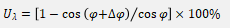
Note [3]: Calculation formula: ![微信图片_20230828192808]() |
6.10 Pulse Frequency Output of TD1880 Multifunction Calibrator
Range [1] | Resolution | Accuracy(Tcal ± 5°C) ± (ppm*RD + μHz) | Jitter |
1.000000 Hz ≤ F ≤ 9.999999 Hz | 1 μHz | 20 + 20 | <2 ns |
10.00000 Hz ≤ F ≤ 99.99999 Hz | 10 μHz |
100.0000 Hz ≤ F ≤ 999.9999 Hz | 0.1 mHz |
1.000000 kHz ≤ F ≤ 9.999999 kHz | 1 mHz |
10.00000 kHz ≤ F ≤ 99.99999 kHz | 10 mHz |
100.0000 kHz ≤ F ≤ 999.9999 kHz | 0.1 Hz |
1.000000 MHz ≤ F ≤ 2.000000 MHz | 1 Hz |
Note [1]: The output type is TTL level. |
6.11 Capacitance(optional) of TD1880 Multifunction Calibrator
Range | Measurement Uncertainty (k=2) (Tcal±5℃) %*output + floor | Resolution | Allowable Operating Frequency Or Charge And Discharge Rate |
90 days | 1 year |
1.100 0 nF~3.299 9 nF | 0.4 + 0.04 nF | 0.5 + 0.04 nF | 0.1 pF | 10 Hz~3 kHz |
3.300 0 nF~10.999 9 nF | 0.2 + 0.04 nF | 0.25 + 0.04 nF | 0.1 pF | 10 Hz~1 kHz |
11.000 0 nF~32.999 9 nF | 0.2 + 0.4 nF | 0.25 + 0.4 nF | 0.1 pF | 10 Hz~1 kHz |
33.000 nF~109.999 nF | 0.2 + 0.4 nF | 0.25 + 0.4 nF | 1 pF | 10 Hz~1 kHz |
110.000 nF~329.999 nF | 0.2 + 0.3 nF | 0.25 + 0.3 nF | 1 pF | 10 Hz~1 kHz |
0.330 00 μF~1.099 99 μF | 0.2 + 1 nF | 0.25 + 1 nF | 10 pF | 10 Hz~600 Hz |
1.100 00 μF~3.299 99 μF | 0.2 + 3 nF | 0.25 + 3 nF | 10 pF | 10 Hz~300 Hz |
3.300 0 μF~10.999 9 μF | 0.2 + 10 nF | 0.25 + 10 nF | 100 pF | 10 Hz~150 Hz |
11.000 μF~32.999 9 μF | 0.32 + 30 nF | 0.40 + 30 nF | 100 pF | 10 Hz~120 Hz |
33.000 μF~109.999 μF | 0.36 + 100 nF | 0.45 + 100 nF | 1 nF | 10 Hz~80 Hz |
110.000 μF~329.999 μF | 0.36 + 300 nF | 0.45 + 300 nF | 1 nF | 0 Hz~50 Hz |
0.330 00 mF~1.099 99 mF | 0.36 + 1 μF | 0.45 + 1 μF | 10 nF | 0 Hz~20 Hz |
1.100 00 mF~3.299 99 mF | 0.36 + 3 μF | 0.45 + 3 μF | 10 nF | 0 Hz~6 Hz |
3.300 0 mF~10.999 9 mF | 0.36 + 10 μF | 0.45 + 10 μF | 100 nF | 0 Hz~2 Hz |
11.000 0 mF~30.000 0 mF | 0.6 + 30 μF | 0.75 + 30 μF | 100 nF | 0 Hz~0.6 Hz |
| Note[1]: Output is continuously adjustable. |
6.12 Thermocouple Output and Measurement(optional) of TD1880 Multifunction Calibrator
Type | Output Range °C | Accuracy (k=2)(Tcal±5°C) °C |
min | max | 90days | 1year |
B | 410 | 600 | 0.30 | 0.35 |
600 | 900 | 0.30 | 0.31 |
900 | 1800 | 0.26 | 0.30 |
E | -200 | 0 | 0.10 | 0.11 |
0 | 600 | 0.07 | 0.08 |
600 | 1000 | 0.09 | 0.10 |
J | -200 | -100 | 0.12 | 0.13 |
-100 | 750 | 0.09 | 0.09 |
750 | 1200 | 0.10 | 0.10 |
K | -200 | -100 | 0.15 | 0.20 |
-100 | 1000 | 0.10 | 0.10 |
1000 | 1370 | 0.12 | 0.12 |
N | -200 | -100 | 0.20 | 0.25 |
-100 | 400 | 0.12 | 0.12 |
400 | 1300 | 0.10 | 0.12 |
R | -50 | 50 | 0.30 | 0.40 |
50 | 300 | 0.28 | 0.32 |
300 | 1000 | 0.22 | 0.23 |
1000 | 1750 | 0.25 | 0.25 |
S | -50 | 50 | 0.30 | 0.40 |
50 | 300 | 0.31 | 0.34 |
300 | 1000 | 0.24 | 0.24 |
1000 | 1750 | 0.22 | 0.23 |
T | -200 | 100 | 0.17 | 0.25 |
-100 | 0 | 0.08 | 0.11 |
0 | 400 | 0.08 | 0.08 |
Note [1]: Resolution: 0.01 °C Note [2]: Output source internal resistance: 10 Ω Note [3]: Does not include thermocouple error Note [4]: When using external compensation, S, R, B, K, N, E, J, T conform to the ITS-90 international temperature standard. |
6.13 RTD Output(optional) of TD1880 Multifunction Calibrator
Type | Output Range [1] °C | Accuracy, (Tcal±5°C) °C |
Min | Max | 90 days | 1 year |
Pt385, 100 Ω | -200 | 0 | 0.05 | 0.05 |
0 | 300 | 0.08 | 0.08 |
300 | 850 | 0.12 | 0.12 |
Pt385, 200 Ω | -200 | 250 | 0.04 | 0.04 |
250 | 630 | 0.10 | 0.15 |
Pt385, 500 Ω | -200 | -30 | 0.36 | 0.40 |
-30 | 630 | 0.10 | 0.11 |
Pt385, 1000 Ω | -200 | 0 | 0.027 | 0.03 |
0 | 300 | 0.054 | 0.06 |
300 | 600 | 0.063 | 0.07 |
Cu50 | -50 | 150 | 0.09 | 0.09 |
Cu100 | -50 | 150 | 0.045 | 0.045 |
Note[1]: Resolution: 0.001°C |
7. General Specifications of TD1880 Multifunction Calibrator
Maximum power consumption | 500 VA |
Warm up time | Twice the time since last warmed up, to a maximum of 30 minutes. |
Temperature performance | Operating temperature: 0°C ~ 50°C Calibration temperature: 15°C ~35°C Storage temperature: -20°C ~ 50°C |
Humidity performance | Operating humidity: <80% @ 30°C, <70% @ 40°C, <40% @ 50°C Storage humidity: <95%, No condensation |
Communication interface | RS232×1, USB×1, LAN×1 |
Dimensions
| 440 mm(W)× 462 mm (D) × 206 mm (H) , Handles and feets excluded. |

|
Weight | About 24 kg |
8. Ordering Information of TD1880 Multifunction Calibrator

|
Function | TD1880A | TD1880B |
AC/DC Voltage standard source (U) | ★ | ★ |
AC/DC current standard source (I) | ★ | ★ |
Simulated DC resistance (R) | ★ | ★ |
AC/DC power output (P) | ★ | ★ |
Square wave frequency output (F) | ★ | ★ |
Simulated capacitance (C) | — | ★ |
Simulated TC output &TC measurement(TC) | — | ★ |
Simulated RTD output (RTD) | — | ★ |


")
")
")