TD1860
TUNKIA
Availability: | |
---|---|
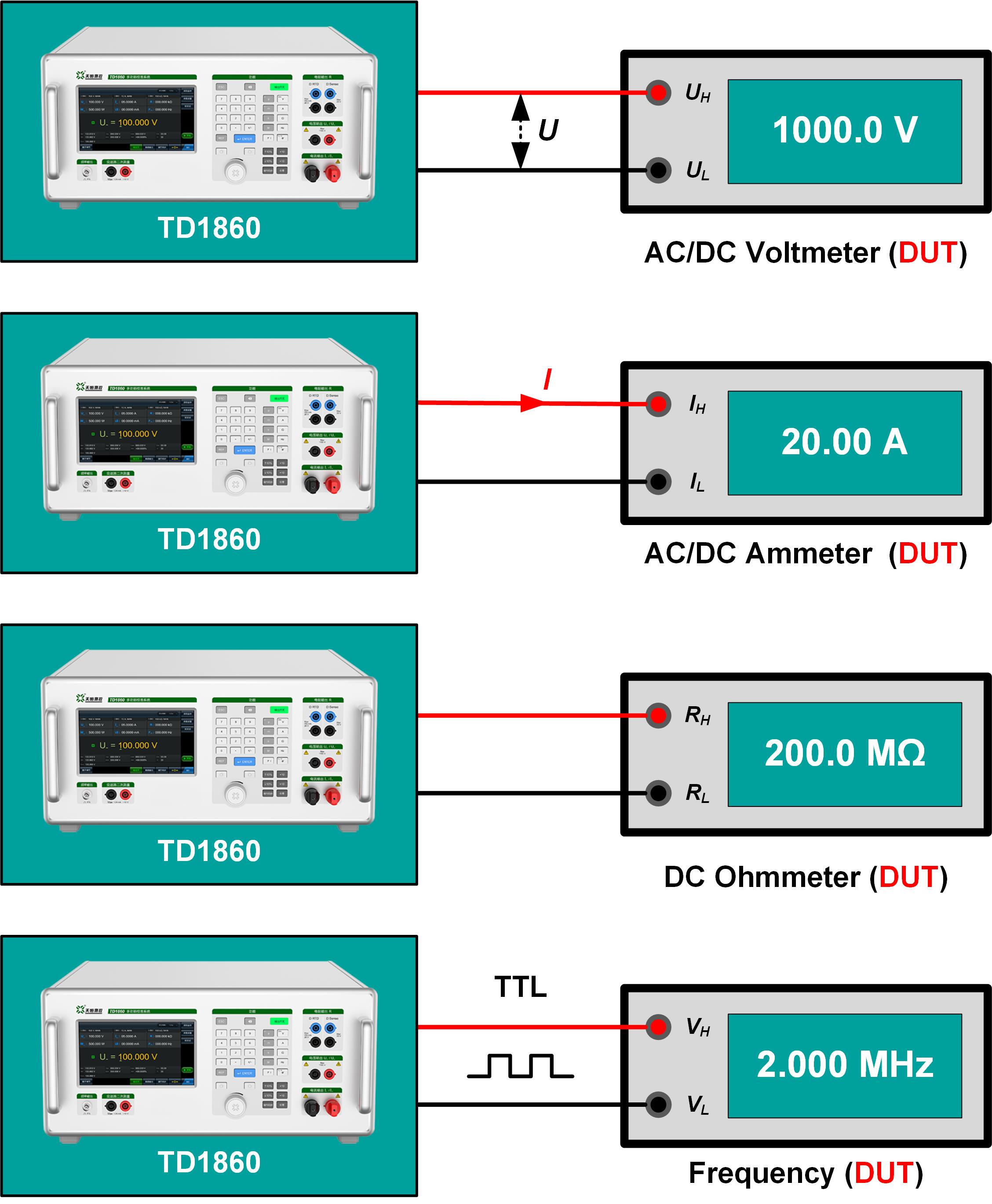
TD1860 is a multi-function calibrator with wide range and high precision, integrates AC\DC voltage source, AC\DC current source, DC resistance source, etc. The DC accuracy class is up to 0.01, and the AC accuracy class is up to 0.05. It’s applied for calibrating 4.5 digits multimeter, voltmeter, ammeter, ohmmeter, power meter.
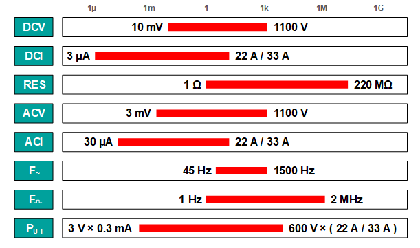
• DC voltage output: ± (10 mV ~ 1100 V)
• DC current output: ± (3 μA ~ 22 A)(33 A optional)
• AC voltage output: 3 mV ~ 1100 V
• AC current output: 30 μA ~ 22 A(33 A optional)
• Sinusoidal wave frequency: 45 Hz ~ 1500 Hz
• Simulated DC resistance:0 Ω ~ 220 MΩ, Continuously adjustable
• 2 MHz square wave frequency output
• Phase output
• AC/DC power output
• Multiple value output modes
• Remote adjustment(optional)
• Clamp meter calibration(optional)
• Transducer calibration(optional)
• 7.0-inch Color Touch Screen
☆Calibrate AC\DC electrical measuring instruments |
• DCV output: ± (10 mV ~ 1100 V) • DCI outpu: ± (3 μA ~ 22 A or 33 A) • ACV output: 3 mV ~ 1100 V, 45 Hz ~ 1500 Hz • ACI output: 30 μA ~ 22 A or 33 A, 45 Hz ~ 1500 Hz • RES output: 0 Ω ~ 220 MΩ • Frequency output: 1 Hz ~ 2 MHz • Suitable for calibrating 4.5-digit and below digital multimeters, class 0.05 and below DC voltmeters, class 0.1 and below DC ammeters and DC resistance meters, class 0.2 and below AC voltmeters and ammeters, and 0.01-level and below frequency meters. |
☆Calibrate AC\DC power meters |
•Application: The virtual power standard source composed of independent outputs of AC/DC voltage (DCV/ACV) and AC/DC current (DCI/ACI) with adjustable phase is suitable for calibrating AC/DC power meters. •Suitable for calibrating DC power meters of class 0.2 and below, active power meters of class 0.5 and below, reactive power meters, apparent power meters, power frequency phase meters and power factor meters. |
☆ Calibrate clamp ammeter (optional) |
• Users can choose TD1020 current coil (50 T), pass 20 A AC and DC standard current, and achieve equivalent current output of up to 1000 At, which is suitable for calibrating clamp ammeters or current clamps with lower accuracy levels of level 1 and below. • If you need to calibrate a clamp ammeter with higher accuracy, you can choose clamp ammeter calibration device products such as TD1040 or TD1050A from Tunkia. |
☆Calibrate AC/DC Transducer (optional) |
• DC small-signal measurement. (Vmax: 12 V, Imax: 24 mA) • Calibrate the proportional error of AC/DC voltage/current transducer. |
☆Front\Side Panel | |
S/N | Description |
LCD touch screen: intuitive display of multiple power levels and touch operation greatly improves the usability of the instrument. | |
Pulse frequency output terminal: BNC Female. | |
Input terminals for transducer: Supports input of maximum DC 24 mA or 12 V signal. | |
Operation panel: A variety of value input and adjustment modes greatly improve the instrument's ease of operation. | |
Foldable feet: Slightly raise the instrument to a certain angle to obtain the best operating and reading angle | |
AC/DC current output terminals. Can be connected to Φ4 gun plug or U-shaped plug, maximum current supported is 22 A or 33 A. | |
AC/DC voltage output terminals: Protective terminal blocks are used to prevent high voltage hazards caused by improper operation. | |
Simulated DC resistance output terminals: Two-wire or four-wire connection can be selected. |
☆Rear panel | |
S/N | Description |
Remote box interface: Connect the remote control box (option) via the control cable. | |
RS232 communication interface: Can be connected to a computer to facilitate user programming and control of the output of the multi-functional standard source. | |
Cooling vents: The built-in radiator and fan are used to dissipate heat to ensure the stability of the internal temperature of the instrument and improve the measurement accuracy. | |
Chassis ground binding post: The instrument should be grounded before operation to ensure electrical safety. | |
AC 220V power interface: Rocker switch, AC 220V power input interface with fuse. | |
Foldable feet: Improve the anti-slip performance when the instrument is placed, and prevent the panel from being scratched when the instrument is slightly moved. | |
Handle: The front and rear panels are each equipped with a pair of handles to facilitate users to move or carry the instrument, and also to protect the various connection terminals or interfaces on the front and rear panels of the instrument from being bumped or damaged during movement or transportation. |
☆Wide output range |
|
☆High stability and accuracy |
|
☆ High load capacity |
|
☆ 4-terminals Simulated DC resistance |
☑ Continuously adjustable, with better adjustment fineness and sensitivity ☑ Smaller size and lighter weight ☑No influence of transfer switch error, residual resistance error and contact resistance error. |
☆ Safety protection function |
|
☆ Easy to operate |
|
☆ Multiple output\adjustment methods |
|
|
☆Multiple output & adjustment methods |
|
|
☆Multiple output & adjustment methods |
|
☆ Dedicated test software (option) |
|
Range | Resolution | Stability | Uncertainty (k=2)[1] | Max Burden (mA) | Ripple Factor (%) | |
24 hours (23±1)°C | 90 days (23±5)°C | 1 year (23±5)°C | ||||
ppm*RD + μV[2] | ||||||
100 mV | 1 μV | 40 + 5 | 64 + 10 | 80 + 10 | 300 | <0.5 |
300 mV | 1 μV | 40 + 5 | 64 + 10 | 80 + 10 | 300 | <0.5 |
1 V | 10 μV | 40 + 10 | 64 + 15 | 80 + 15 | 300 | <0.5 |
3 V | 10 μV | 40 + 10 | 64 + 15 | 80 + 15 | 300 | <0.5 |
10 V | 100 μV | 40 + 100 | 64 + 150 | 80 + 150 | 600 | <0.5 |
30 V | 100 μV | 40 + 150 | 64 + 150 | 80 + 150 | 800 | <0.5 |
100 V | 1 mV | 40 + 1500 | 64 + 1500 | 80 + 1500 | 300 | <0.5 |
300 V | 1 mV | 40 + 1500 | 64 + 1500 | 80 + 1500 | 120 | <0.5 |
1000 V | 10 mV | 40 + 5000 | 64 + 5000 | 80 + 5000 | 40 | <0.5 |
Note[1]: When the output is negative, the floor uncertainly is double. For example, when the output is -1 V, the accuracy is (80 ppm ×1 V + 30 μV); [2]: RD is the reading value, the same below. |
• Output range: ± (10 mV ~ 1100 V)
• Short-circuit and overload protection
Range | Resolution | Stability | Uncertainty (k=2)[1] | Compliance Voltage (V) | Ripple Factor (%) | |
24 hours (23±1)°C | 90 days (23±5)°C | 1 year (23±5)°C | ||||
ppm*RD + μA | ||||||
30 μA | 100 pA | 96 + 0.02 | 108 + 0.02 | 120 + 0.02 | 11 | <0.5 |
100 μA | 1 nA | 96 + 0.04 | 108 + 0.04 | 120 + 0.04 | 11 | <0.5 |
300 μA | 1 nA | 96 + 0.04 | 108 + 0.04 | 120 + 0.04 | 11 | <0.5 |
1 mA | 10 nA | 96 + 0.08 | 108 + 0.08 | 120 + 0.08 | 11 | <0.5 |
3 mA | 10 nA | 96 + 0.08 | 108 + 0.08 | 120 + 0.08 | 11 | <0.5 |
10 mA | 100 nA | 96 + 0.8 | 108 + 0.8 | 120 + 0.8 | 11 | <0.5 |
30 mA | 100 nA | 96 + 0.8 | 108 + 0.8 | 120 + 0.8 | 11 | <0.5 |
100 mA | 1 μA | 96 + 8 | 108 + 8 | 120 + 8 | 11 | <0.5 |
300 mA | 1 μA | 96 + 24 | 108 + 24 | 120 + 24 | 4 | <0.5 |
1 A | 10 μA | 96 + 80 | 108 + 80 | 120 + 80 | 3.5 | <0.5 |
3 A | 10 μA | 96 + 80 | 108 + 80 | 120 + 80 | 4 | <0.5 |
10 A | 100 μA | 96 + 800 | 108 + 800 | 120 + 800 | 3.5 | <0.5 |
20 A(30 A)[2] | 100 μA | 96 + 800 | 108 + 800 | 120 + 800 | 2.8 | <0.5 |
Note [1]: When the output is negative, the floor uncertainly is double; Note [2]: 30 A range is optional. |
• Output range: ± (3 μA ~ 22 A or 33 A)
• Open-circuit and overload protection
Range | Resolution | Uncertainty (k=2) | Allowable Current | |
90days(23 ± 5)°C | 1year(23 ± 5)°C | |||
ppm*RD + Ω | ||||
0 Ω | — | 5 mΩ | 5 mΩ | 1mA~ 300mA |
10 Ω | 100μΩ | 240 + 0.015 | 300 + 0.015 | 1mA~ 150 mA |
30 Ω | 100μΩ | 240 + 0.015 | 300 + 0.015 | 1mA~ 150 mA |
100 Ω | 1 mΩ | 120 + 0.015 | 150 + 0.015 | 1mA~ 80 mA |
300 Ω | 1 mΩ | 120 + 0.03 | 150 + 0.03 | 1mA~ 40 mA |
1 kΩ | 10 mΩ | 80 + 0.1 | 100 + 0.1 | 1mA~ 20 mA |
3kΩ | 10 mΩ | 80 + 0.2 | 100 + 0.2 | 0.1mA~ 6mA |
10 kΩ | 100 mΩ | 80 + 1 | 100 + 1 | 0.1mA~ 2mA |
30 kΩ | 100 mΩ | 80 + 2 | 100 + 2 | 10μA~ 600 μA |
100 kΩ | 1 Ω | 80 + 10 | 100 + 10 | 10μA~ 200 μA |
300 kΩ | 1 Ω | 80 + 20 | 100 + 20 | 1μA~ 60 μA |
1 MΩ | 10 Ω | 80 + 100 | 100 + 100 | 1μA~ 20 μA |
3 MΩ | 10 Ω | 80 + 300 | 100 + 300 | 0.25μA~ 6 μA |
10 MΩ | 100 Ω | 240 + 1k | 300 + 1k | 0.25μA~ 2 μA |
30 MΩ | 100 Ω | 400 + 3k | 500 + 3k | 25nA~600nA |
100 MΩ | 1kΩ | 1600 + 80k | 2000 + 80k | 25nA~200nA |
200 MΩ | 1kΩ | 4000 + 100k | 5000 + 100k | 2.5nA~ 45nA |
• Output range: 0 Ω ~ 220 MΩ
• Over-current and reverse connection protection
Range | Resolution | Frequency (Hz) | Uncertainty (k=2) | Max Burden (mA) [Source internal resistance] | Harmonic (%) | |
90 days (23±5)°C | 1 year (23±5)°C | |||||
ppm*RD + mV | ||||||
30 mV | 100 nV | 45≤F≤1k | 360 + 0.03 | 400 + 0.03 | [1Ω] | <0.5 |
1k<F≤1.5k | 540 + 0.03 | 600 + 0.03 | <0.5 | |||
100 mV | 1 μV | 45≤F≤1k | 360 + 0.03 | 400 + 0.03 | [1Ω] | <0.5 |
1k<F≤1.5k | 540 + 0.03 | 600 + 0.03 | <0.5 | |||
300 mV | 1 μV | 45≤F≤1k | 270 + 0.05 | 300 + 0.05 | 100 | <0.5 |
1k<F≤1.5k | 450 + 0.05 | 500 + 0.05 | <0.5 | |||
1 V | 10 μV | 45≤F≤1k | 270 + 0.2 | 300 + 0.2 | 300 | <0.5 |
1k<F≤1.5k | 450 + 0.2 | 500 + 0.2 | <0.5 | |||
3 V | 10 μV | 45≤F≤1k | 360 + 0.2 | 400 + 0.2 | 300 | <0.5 |
1k<F≤1.5k | 450 + 0.2 | 500 + 0.2 | <0.5 | |||
10 V | 100 μV | 45≤F≤1k | 270 + 2 | 300 + 2 | 500 | <0.5 |
1k<F≤1.5k | 450 + 2 | 500 + 2 | <0.5 | |||
30 V | 100 μV | 45≤F≤1k | 360 + 2 | 400 + 2 | 800 | <0.5 |
1k<F≤1.5k | 450 + 2 | 500 + 2 | <0.5 | |||
100 V | 1 mV | 45≤F≤1k | 270 + 20 | 300 + 20 | 400 | <0.5 |
1k<F≤1.5k | 450 + 20 | 500 + 20 | <0.5 | |||
300 V | 1 mV | 45≤F≤1k | 360 + 20 | 400 + 20 | 120 | <0.5 |
1k<F≤1.5k | 450 + 20 | 500 + 20 | <0.5 | |||
1000 V | 10 mV | 45≤F≤1k | 270 + 200 | 300 + 200 | 40 | <0.5 |
1k<F≤1.5k | 450 + 200 | 500 + 200 | <0.5 |
• Output range: 3 mV ~ 1100 V
• Short-circuit and overload protection
Range | Resolution | Frequency (Hz) | Uncertainty (k=2) | Compliance Voltage (V) | Harmonic (%) | |
90 days (23±5)°C | 1 year (23±5)°C | |||||
ppm*RD + μA | ||||||
300 μA | 1 nA | 45≤F≤1k | 360 + 0.12 | 400 + 0.12 | 50 | <0.5 |
1k<f≤1.5k | 450 + 0.12 | 500 + 0.12 | <0.5 | |||
3 mA | 10 nA | 45≤F≤1k | 270 + 0.6 | 300 + 0.6 | 50 | <0.5 |
1k<f≤1.5k | 360 + 0.6 | 400 + 0.6 | <0.5 | |||
30 mA | 100 nA | 45≤F≤1k | 270 + 6 | 300 + 6 | 50 | <0.5 |
1k<f≤1.5k | 360 + 6 | 400 + 6 | <0.5 | |||
300 mA | 1 μA | 45≤F≤1k | 270 + 60 | 300 + 60 | 15 | <0.5 |
1k<f≤1.5k | 360 + 60 | 400 + 60 | <0.5 | |||
1 A | 10μA | 45≤F≤1k | 270 + 200 | 300 + 200 | 15 | <0.5 |
1k<f≤1.5k | 360 + 200 | 400 + 200 | <0.5 | |||
5 A | 10μA | 45≤F≤1k | 270 + 600 | 300 + 600 | 4 | <0.5 |
1k<f≤1.5k | 360 + 600 | 400 + 600 | <0.5 | |||
20 A (30 A)[1] | 100μA | 45≤F≤1k | 270 + 4000 | 300 + 4000 | 2.5 | <0.5 |
1k<f≤1.5k | 360 + 4000 | 400 + 4000 | <0.5 | |||
Note [1]: 30 A range is optional. |
• Output range: 30 μA ~ 22 A or 33 A
• Open-circuit and overload protection
Range[1] | Resolution | Uncertainty (k=2) |
45.0000 Hz ≤ F ≤ 99.9999 Hz | 0.0001 Hz | 0.01% |
100.000 Hz ≤ F ≤ 999.999 Hz | 0.001 Hz | 0.01% |
1000.00 Hz ≤ F ≤ 1500.00 Hz | 0.01 Hz | 0.01% |
Note [1]: The output mode is AC voltage or AC current. |
Frequency Range (f) | Voltage Range (U) | Current Range (I) | Optimum Uncertainty (k=2) %*power output [1][2] |
DC | 10 mV ~ 1100 V | 3μA ~ 22 A/33 A | 0.05 |
45 Hz ~ 65 Hz | 3 V ~ 600 V | 0.3 mA ~ 22 A/33 A | 0.1 |
Phase | Power Factor | Uncertainty (k=2) | ||
WATTS | VARS | λ=cosφ | Phase | Power Factor |
0° | 90° | 1.00000 | 0.05° | 0.000% |
10° | 80° | 0.98481 | 0.05° | 0.015% |
20° | 70° | 0.93969 | 0.05° | 0.032% |
30° | 60° | 0.86603 | 0.05° | 0.050% |
40° | 50° | 0.76604 | 0.05° | 0.073% |
50° | 40° | 0.64279 | 0.05° | 0.104% |
60° | 30° | 0.50000 | 0.05° | 0.151% |
70° | 30° | 0.34202 | 0.05° | 0.240% |
80° | 10° | 0.17365 | 0.05° | 0.495% |
90° | 0° | 0.00000 | — | — |
Range [1] | Resolution | Uncertainty (k=2) | Shake |
1.000 00 Hz ≤ F ≤ 9.999 99 Hz | 10 μHz | 20 ppm*RD + 20 μHz | <20 ns |
10.000 0 Hz ≤ F ≤ 99.999 9 Hz | 0.1 mHz | ||
100.000 Hz ≤ F ≤ 999.999 Hz | 1 mHz | ||
1.000 00 kHz ≤ F ≤ 9.999 99 kHz | 10 mHz | ||
10.000 0 kHz ≤ F ≤ 99.999 9 kHz | 0.1 Hz | ||
100.000 kHz ≤ F ≤ 999.999 kHz | 1 Hz | ||
1.000 00 MHz ≤ F ≤ 2.000 00 MHz | 10 Hz | ||
Note [1]: The output type is TTL level. |
Type | Range | Measurement Range | Uncertainty (k=2) |
DCV | 1 V | ± (0 ~ 1.2) V | 0.006%*RD + 0.004%*RG |
10 V | ± (0 ~ 12) V | 0.006%*RD + 0.004%*RG | |
DCI | 2 mA | ± (0 ~ 2.4) mA | 0.006%*RD + 0.004%*RG |
20 mA | ± (0 ~ 24) mA | 0.006%*RD + 0.004%*RG |
Power supply | AC (220±22) V,(50±2) Hz |
Maximum power consumption | 600 VA |
Warm up time | 30 minutes. |
Temperature performance | Operating temperature:0°C~40°C Calibration temperature:18°C~28°C Storage temperature:-20°C~70°C |
Humidity performance | Operating humidity:<80% @ 30°C,<70% @ 40°C Storage humidity:(20%~80%) R·H,No condensation |
Altitude | <3000 m |
Communication interface | RS232 |
Dimensions | 450 mm(W)×505 mm (D) ×203 mm (H), excluding handles and feets. |
Weight | About 25kg |