TD3650 Three-phase Energy Meters Verification Device

1. Summary
TD3650 is a new-generation comprehensive three-phase energy meter testing device designed to meet the requirements of OIML R46, the new Chinese national standard GB/T 17215.211, the type evaluation outline JJF 1245-2019, and the latest technical specifications for smart meters from State Grid and China Southern Power Grid.
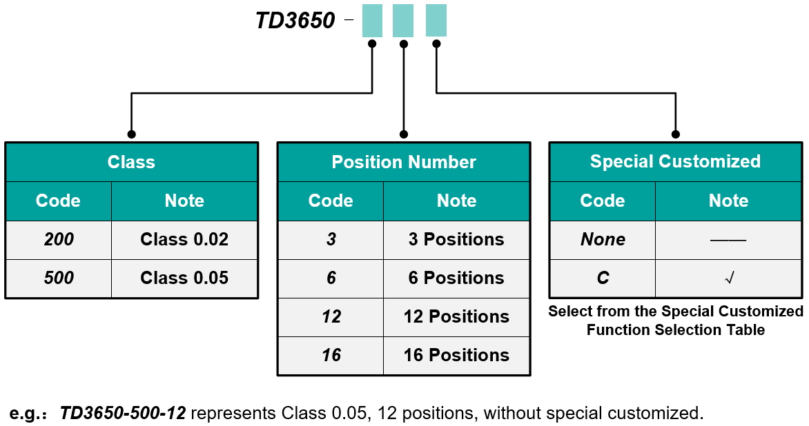
It mainly consists of a three-phase precision standard power source, a multi-position meter test bench, a control console, an optional computer, and dedicated software. Available in two accuracy classes—0.02 and 0.05—it supports fully automatic simultaneous verification of 3 to 16 three-phase electronic energy meters, smart meters, or IoT meters with identical voltage/current ranges but different meter constants.
2. Features
2.1 Basic Features
Maximum Output Capacity: 576 V / 120 A, with fundamental frequency ranging from 45 Hz to 100 Hz.
Minimum Current Output: As low as 0.2 mA, meeting the starting test requirements for Class D/E energy meters with Imax of 1.2 A.
Three-Phase Power Adjustment: Supports both unified and per-phase adjustment of voltage and current outputs. Fully automatic range switching and load matching simplify testing.
Multifunctional Energy Measurement: Supports measurement of forward and reverse active energy, reactive energy, and other energy types.
Harmonic Output Function: Supports 2nd to 63rd harmonics at 50 Hz / 60 Hz. Harmonic amplitude and phase are programmable, enabling high-order harmonic scanning and complex waveform testing.
High-Order Harmonic Testing: Built-in testing plans automatically superimpose sweep signals from 15fnom to 40fnom onto the voltage and current circuits, collecting data at each harmonic frequency to evaluate error deviation caused by harmonics.
Complex Waveform Testing: Preloaded with common waveforms such as square waves, peaked waves, sub-harmonics, and odd harmonics. Custom complex waveforms can also be defined by users for influence quantity testing.
DC / Even Harmonic Testing: Equipped with the TD3410 half-wave rectification waveform test module to perform DC and even harmonic testing.
Daily Timing Error Test: Built-in standard time clock tester with a daily timing error limit of ±0.05 s/day.
Automatic Inspection: Supports automated inspection and auto-short-circuiting of empty meter positions.
Clamping-Type Wiring: Features a dedicated clamping meter holder compatible with State Grid and Southern Grid meter outlines, allowing for quick and convenient testing. Non-standard meters can be connected via adjustable terminals or manual wiring.
Communication Interface: Communicates with the meter under test via RS-485 interface, supporting both DL/T 645 and 698 protocols.
Energy Pulse Sampling: Equipped with both electrical pulse and optical pulse sampling ports.
Management Platform Interface: Complies with data upload specifications of State Grid and Southern Grid metering production management platforms.
Multi-Position Test Bench: Available with 3, 6, 12, or 16 meter positions. Each position is equipped with power output, energy pulse, and communication interfaces.
Mobile Control Console: Features a touchscreen LCD for real-time observation and manual control of output values during testing.
Dedicated Calibration Software: Supports semi-automatic or fully automatic calibration of the meter under test, with data management and certificate export capabilities. Also features multi-test per point, user-defined test intervals, and automatic plotting of error curves.
Resume from Breakpoint: In the event of a power outage or reboot, the software can resume testing from the last recorded error point.
High Reliability: Output channels are well protected with fault detection and recovery capabilities, ensuring excellent maintainability.
2.2 Optional Features
Single and Three-Phase Compatibility: Optional isolated voltage transformers can be added to support single-phase meter testing. Manual wiring is available for single-phase meters. Supports up to 12 meter positions.
CT Isolation: Optional isolated current transformers allow for non-disconnection (non-breaking) testing of energy meters, with support for up to 12 meter positions.
Auxiliary Power Supply: AC/DC 100 V–240 V input, supports auxiliary power line consumption tests and voltage variation tests.
Voltage Power Consumption Test: Optional 1-position voltage consumption test module enables testing of voltage line power consumption.
Current Power Consumption Test: Optional multi-position current consumption test module enables testing of current line power consumption.
Rapid Load Current Switching: Users can set ton and toff durations as well as total test time. Switching between on/off states completes within one nominal frequency cycle, with zero-crossing switching. A single test can run for over 4 hours continuously.
Voltage Dips and Short Interruptions Test: Supports AC voltage dips and short interruptions in voltage supply circuits.
Smart Meter Function Testing: Supports tests for prepaid control, data freezing, key updates, parameter updates, remote control, security authentication, event logging, and communication protocol compliance.
Ground Fault Test: Supports testing under ground fault conditions, including scenarios with a 10% overvoltage. Applicable to three-phase four-wire meters connected to distribution networks with ground fault suppressors or isolated neutral points.
Reference Meter: Optional Class 0.05 / 0.02 standard energy meter or harmonic reference energy meter available.
Harmonic Energy Measurement: Accuracy testing of harmonic energy and harmonic measurement functions using harmonic reference meters.
Bluetooth (Optional): Supports Bluetooth communication in master-slave mode, enabling one-to-one connection with the meter under test.
Optical Probe: Equipped with an optical probe to capture light pulses from energy meters for testing.
3. Verification Items
NO. | Verification Items | Completion (√standard) | Remarks |
1 | Appearance, signs, power check | Observation |
|
2 | Accuracy Test | Initial inherent error test | √ |
|
3 | Starting current test | √ |
|
4 | Test of no-load | √ |
|
5 | Meter constant test | √ |
|
6 | Electric energy display value combination error | √ |
|
7 | Demand indicating value error | √ |
|
8 | A clock test powered by a power supply | √ |
|
9 | Impact of the standby power supply on the clock | √ |
|
10 | Error consistency test | √ |
|
11 | Variation requirement test | √ |
|
12 | The load current rises and falls worse test | √ |
|
13 | Repeat test | √ |
|
14 | EMC | Voltage dips and interruptions | Optional-Fast change test of load current |
|
15 | Resistance to Other Influences | Harmonic in voltage-current circuits –the 5st harmonic test | √ |
|
16 | Harmonic in voltage-current circuits - square-wave test | √ |
|
17 | Harmonic in voltage-current circuits - peaked wave test | √ |
|
18 | Interharmonic in the current circuits - the pulse train triggers the waveform | √ |
|
19 | Odd harmonic in voltage-current circuits –waveform test triggered by 90 degree phase | √ |
|
20 | Impact Test of DC and Even Harmonics –waveform of half wave rectification | √ |
|
21 | Load unbalance test | √ |
|
22 | Voltage change test | √ |
|
23 | One or two-phase voltage interruption | √ |
|
24 | Frequency change test | √ |
|
25 | Reverse phase sequence test | √ |
|
26 | Auxiliary power supply voltage change test | Auxiliary power supply (optional) |
|
27 | Burden current fast change test | Burden current fast change test (optional) |
|
28 | Self-heating test | √ |
|
29 | High-order harmonic test | √ |
|
30 | Fault earthing test(Only for three-phase four-wire transformer type energy meter) | Fault earthing test (optional) | Only for class 0.05 TD3650 |
31 | Electrical Performance Test | Power consumption test of voltage circuits | optional |
|
32 | Power consumption test of current circuits | optional |
|
33 | Power consumption test of auxiliary power supply circuit | optional |
|
34 | IOT Electricity Meter | Harmonic power accuracy test | harmonic power(optional)
|
|
35 | Harmonic measurement accuracy test |
|